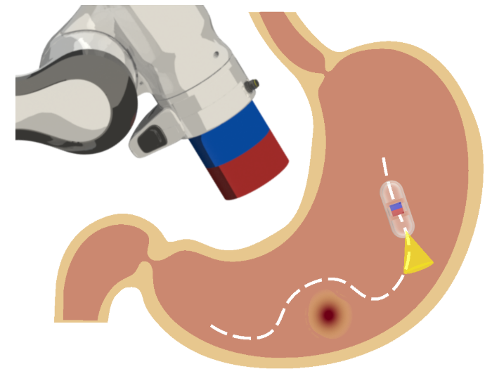
Robotic magnetic manipulation offers a minimally invasive approach to gastrointestinal examinations through capsule endoscopy. However, controlling such systems using external permanent magnets (EPM) is challenging due to nonlinear magnetic interactions, especially when there are complex navigation requirements such as avoidance of sensitive tissues.
In this work, we present a novel trajectory planning and control method incorporating dynamics and navigation requirements, using a single EPM fixed to a robotic arm to manipulate an internal permanent magnet (IPM). Our approach employs a constrained iterative linear quadratic regulator that considers the dynamics of the IPM to generate optimal trajectories for both the EPM and IPM.
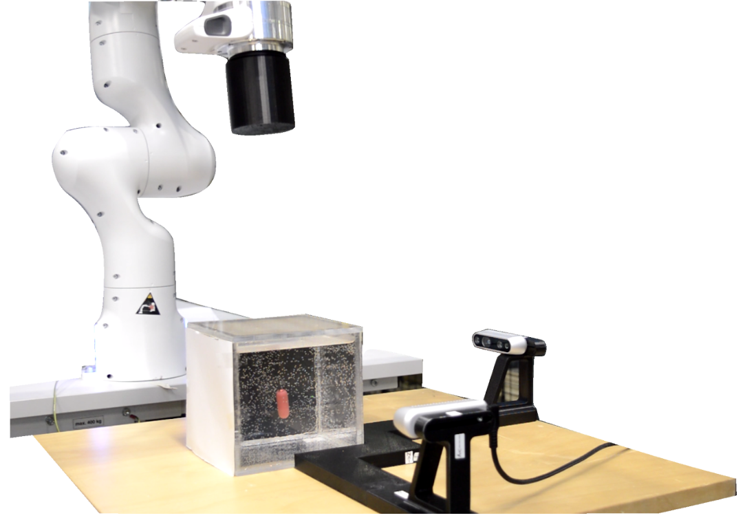
Block diagram of the control and planning phases for robotic magnetic capsule endoscopy. The planning phase (left) utilizes iLQR to generate optimal state trajectories \( \mathbf{x}^* \), input trajectories \( \mathbf{u}^* \), and time-varying optimal controller gains \( \mathbf{K}(k) \), based on user-defined constraints and initial/goal positions. In the control phase (right), joint angles \( \mathbf{q} \) are measured from the robotic arm encoders, and the 3D position of the IPM is obtained through object detection and triangulation using two orthogonal cameras. The Extended Kalman Filter (EKF) then estimates the IPM's position \( \mathbf{p}_I \) and velocity \( \mathbf{v}_I \), which are used to update the control input \( \mathbf{u} \) and follow the optimal trajectories. The system includes the EPM for external magnetic manipulation and the IPM within the targeted environment, with the IPM dimensions shown in the figure and given in millimeters.
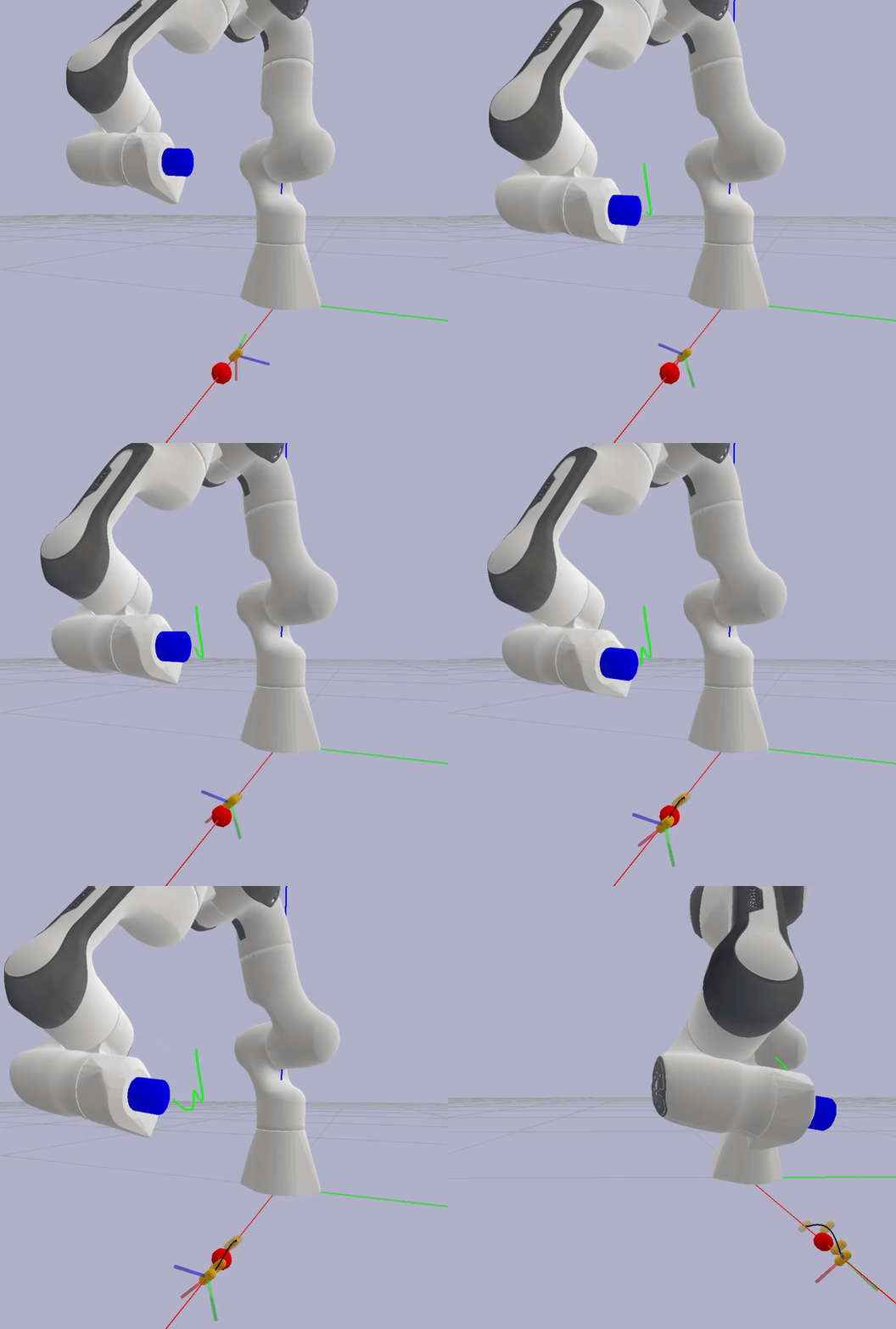
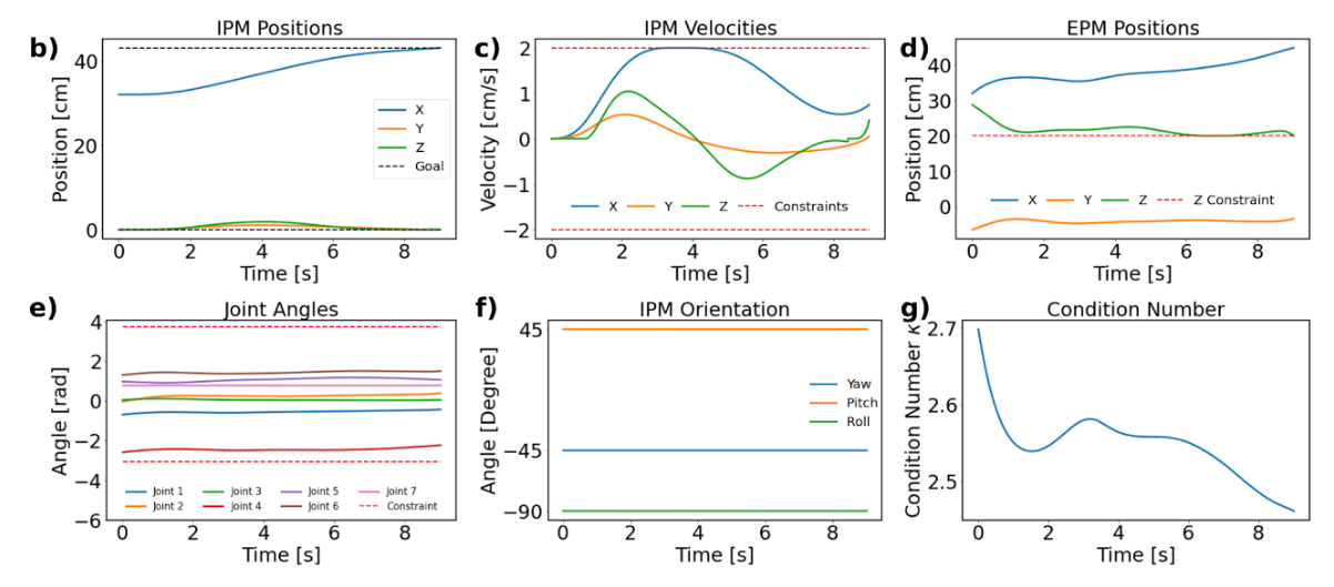
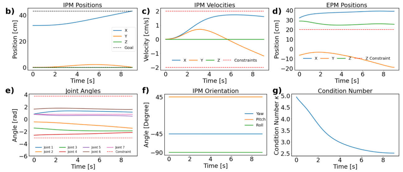
(a) Simulation Case 1 visualization. (b) Time series data of the optimal IPM trajectory. (c) IPM velocities along the trajectory. (d) Time series data of the optimal EPM trajectory. (e) Joint angles of the robotic arm. (f) Time series data of the IPM orientation. (g) Condition number (Κ) analysis of the robotic arm’s manipulability.
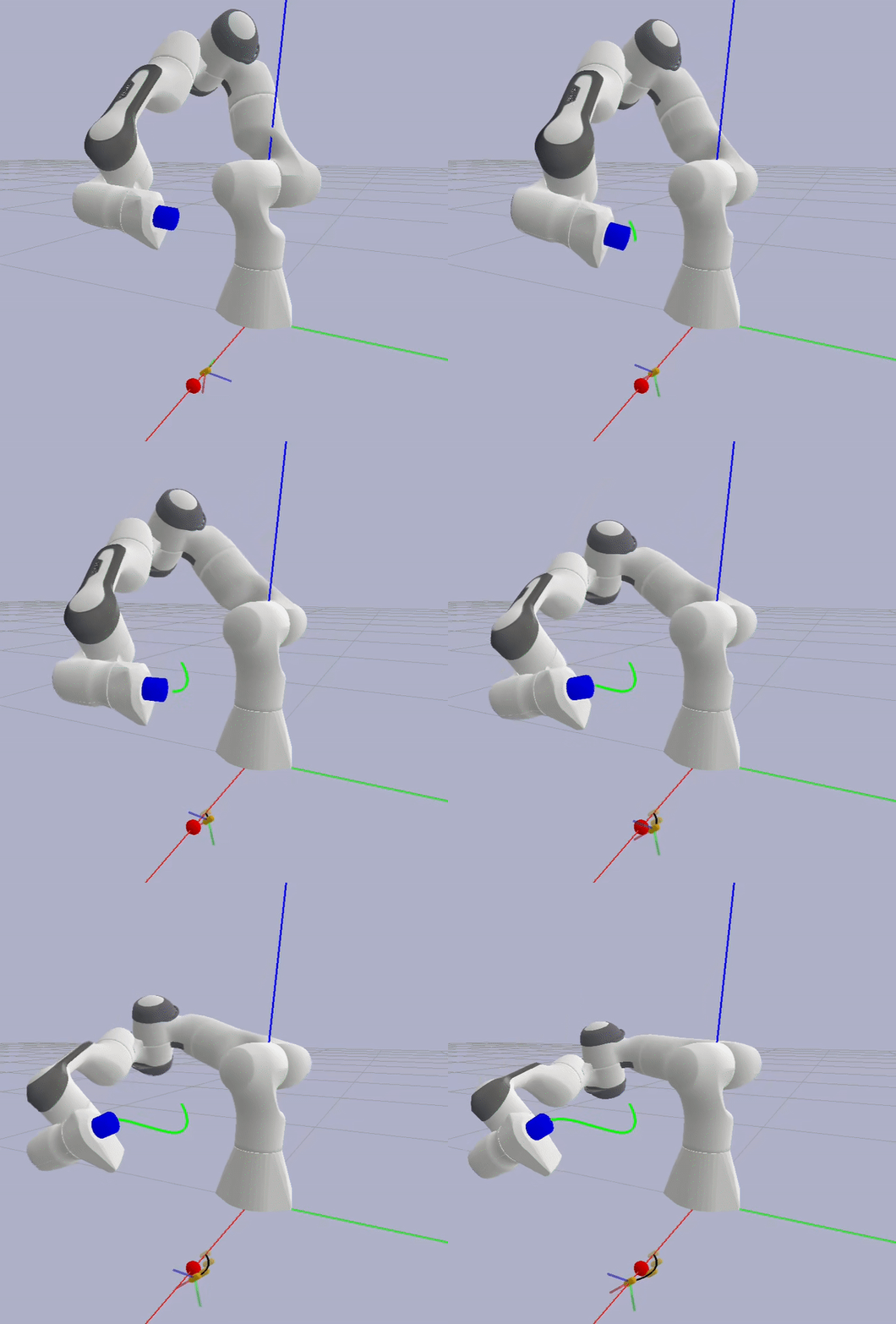
In Case 2, the initial configuration of the robot is chosen to achieve the same IPM position and orientation but with a poorer initial condition number (5, compared to 2.7 in Case 1). The optimal trajectory is designed to improve the condition number over time while adhering to the imposed constraints on position, velocity, joint limits, and orientation.
Real-world experimental results showing repetitive IPM trajectories in 3D space under the given constraints, including obstacle avoidance (red sphere). Each colored line represents an individual trial of the IPM navigating around the obstacle, demonstrating the system's ability to consistently follow the desired path while respecting imposed constraints.
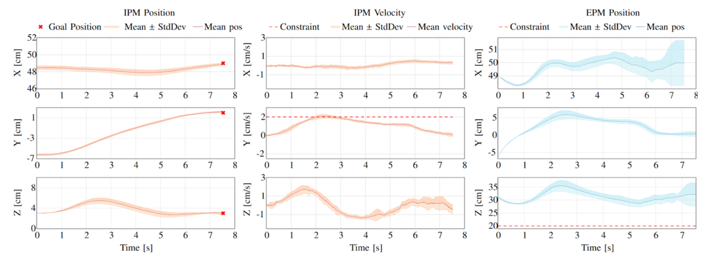
Experimental results showing the time evolution of IPM position, IPM velocity, and EPM position along the X, Y, and Z axes under closed-loop control. The left column shows the IPM position, with mean position (solid line) and standard deviation (shaded area) around the mean, alongside goal positions (red crosses). The middle column displays IPM velocity, with mean velocity and standard deviation, and includes velocity constraints (dashed red line) in the Y-axis plot. The right column represents EPM position with mean position (solid line) and standard deviation (shaded area) around the mean, as well as position constraints in the Z-axis plot (dashed red line). This figure demonstrates the tracking accuracy and stability of both IPM and EPM under the control framework.
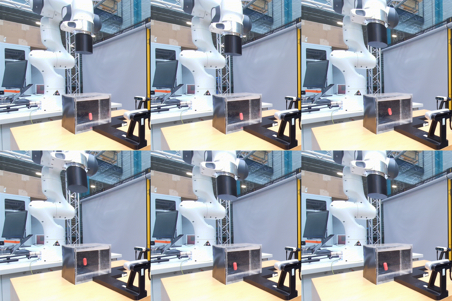
Video of the real-world experimental setup and results, showcasing the robotic magnetic manipulation system in action. The video demonstrates the system's ability to navigate around obstacles and reach the desired goal position while maintaining precise control over the IPM and EPM.
